Raspberry Pi Pico Read Digital Input & Write Digital Output (C/C++ SDK)
In this post, we’ll discuss about GPIO functions using C/C++ SDK. And i also create a demo project to experiment with the Pico I/O operations. This tutorial is compatible with the Rasperry Pi Pico W board and any RP2040-based boards as well.
GPIOs map
The GPIO (General-Purpose Input Output) Pins are the digital IO pins of the Raspberry Pi Pico boards. There are 26 GPIO pins on the Raspberry Pi Pico board below 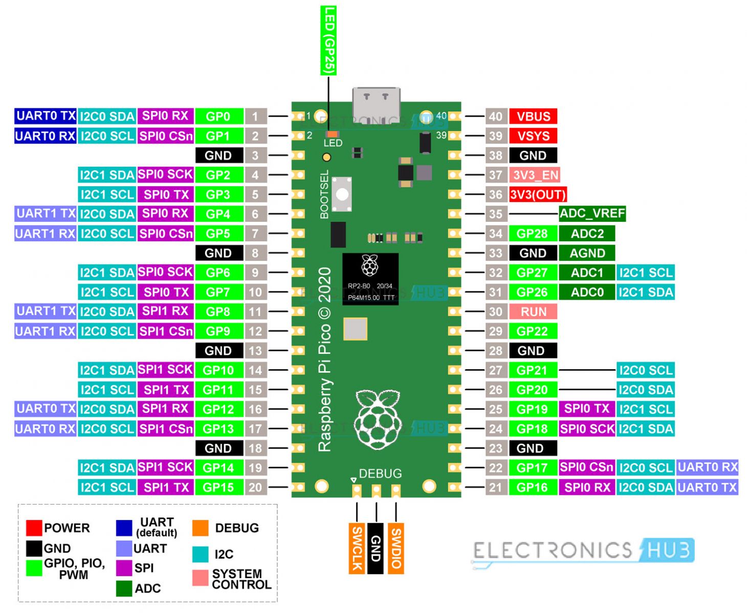
Pin Voltage
In output mode, the digital pin voltage is:
- 3.3v (when the digital pin is set HIGH)
- 0v (when the digital pin is set to LOW)
In input mode, the digital input pin will read bit 0 or 1 depending on the voltage applied to the pin:: - 0v–0.8v: read as 0 (logic 0 or LOW)
- 2v–3.3v: read as 1 (logic 1 or HIGH)
So, any voltage between 0.8v-2v is considered as undefined input voltage level for the digital IO pins.
Special Function GPIO Pins (Non-Usable)
There are 4 GPIO pins that are not “Freely” usable on the Raspberry Pi Pico board. They are not exposed because they’re used to control some features on the Pi Pico board itself. Those pins are as follows:
- GPIO23: Controls the onboard SMPS power save enable pin
- GPIO24: VBUS Sense; HIGH if VBUS is present, Else LOW
- GPIO25: Connected to the onboard LED
- GPIO29: Used by The ADC to measure the VSYS
Raspberry Pi Pico C/C++ SDK GPIO Functions
In SDK folder, you can check all the APIs about GPIOs. Those functions are used for initializing and controlling the IO pins. Below are some basic functions to control IOs, which you can got in /hardware_gpio/include/hardware/gpio
- gpio_init(uint gpio)
Initialise a GPIO for (enabled I/O and set func to GPIO_FUNC_SIO). - gpio_deinit(uint gpio)
Resets a GPIO back to the NULL function, i.e. disables it. - gpio_set_dir(uint gpio, bool mode)
Set a single GPIO direction - gpio_get(uint gpio)
Get a specific GPIO direction - gpio_put(uint gpio, bool value)
Drive a single GPIO high/low
Digital Output Operations
The below code perform how to write output pin with the SDK. In the following example code, GPIO pin number 2(known as built_in LED on rasPico board) as an output pin will toggle every 100ms after initilizing.
1
2
3
4
5
6
7
8
9
10
11
12
13
14
15
#include "pico/stdlib.h"
#include <stdio.h>
#define LED_PIN 2
int main()
{
    gpio_init(LED_PIN);
    gpio_set_dir(LED_PIN, GPIO_OUT);
    while (1)
    {
        gpio_put(LED_PIN, 1);
        sleep_ms(100);
        gpio_put(LED_PIN, 0);
        sleep_ms(100);
    }
}
Read Input State
This is how perform a digital input pin. It will control the output of Pin 5 via the state reading from Pin 6
1
2
3
4
5
6
7
8
9
10
11
12
13
14
int main(){
    gpio_init(5);
    gpio_set_dir(5, GPIO_OUT);
    gpio_init(6);
    gpio_set_dir(6, GPIO_IN);
    while (1)
    {
        while(gpio_get(6))
        {
           gpio_put(5, 1);
        }
        gpio_put(5, 0);
    }
}
LED and Button example
Step #1
1
2
3
mkdir LED_BUTTON
cd LED_BUTTON
vi main.c
then copy that source code into main.c
1
2
3
4
5
6
7
8
9
10
11
12
13
14
15
16
17
18
19
#include "pico/stdlib.h"
#include "
#define BUILTIN_LED PICO_DEFAULT_LED_PIN
#define BTN_PIN 21
int main()
{
    gpio_init(BUILTIN_LED);
    gpio_set_dir(BUILTIN_LED, GPIO_OUT);
    gpio_init(BTN_PIN);
    gpio_set_dir(BTN_PIN, GPIO_IN);
    while (1)
    {
        while(gpio_get(BTN_PIN))
        {
           gpio_put(BUILTIN_LED, 1);
        }
        gpio_put(BUILTIN_LED, 0);
    }
}
Step #2
Create a CMakeLists.txt file to the project’s folder.
1
vi CMakeLists.txt
then copy that code into it.
1
2
3
4
5
6
7
8
9
10
11
12
13
14
15
16
17
18
19
cmake_minimum_required(VERSION 3.13)

include($ENV{PICO_SDK_PATH}/external/pico_sdk_import.cmake)

project(main C CXX ASM)

set(CMAKE_C_STANDARD 11)
set(CMAKE_CXX_STANDARD 17)

pico_sdk_init()

add_executable(${PROJECT_NAME} main.c)

pico_add_extra_outputs(${PROJECT_NAME})

target_link_libraries(${PROJECT_NAME} pico_stdlib)

pico_enable_stdio_usb(${PROJECT_NAME} 1)
pico_enable_stdio_uart(${PROJECT_NAME} 0)
After that, you can do the same as the first blog abt Pico i’ve post. It’s all done.
Simulation with Wokwi
If you dont have hardware kit, you can simulate the result with Wokwi projects. Which is very helpful when you’re just getting started. In another post, i’ll show you guys how to use it in details :>